Reliability of BGA solder joints under mechanical and thermal stresses-Shenzhen Fitech

Reliability of BGA solder joints under mechanical and thermal stresses
BGA (Ball Grid Array Package) is a common integrated circuit packaging technology which has the advantages of large contact area and high signal transmission efficiency. However, BGA solder joints are located at the bottom of the device and are not easy to detect and maintain. Moreover, due to the high level of integration of BGA functions, the solder joints are susceptible to mechanical and thermal stresses, leading to cracking or peeling, which affects the normal operation of the circuit. In this paper, we will analyse the causes of BGA solder joint cracking under stress and propose corresponding control methods.
Mechanical and thermal stresses are the main factors in the cracking of BGA welded joints
Mechanical stress is the interaction force between the internal parts of an object when it is deformed by an external force. bga welded joints may be subjected to mechanical stresses from different directions during assembly and use, such as vibration, impact, bending, etc. These stresses can lead to cracks or even fractures within the solder joint.
Thermal stresses are internal stresses that result from the expansion and contraction deformation of an object due to temperature changes, which are not completely free to deform under the action of external or internal constraints. Under the action of high temperatures, thermal stresses will continue to be generated inside the welded joint, leading to fatigue accumulation and causing the joint to fracture.

Figure 1. cracked BGA solder joint
Excessive IMC thickness can reduce solder joint reliability
IMC is a metal compound formed between the solder and the pad which has an important influence on the strength and reliability of the solder joint. Under lead-free process conditions, the IMC is relatively thicker due to the higher soldering temperature and longer time than in leaded processes. This, combined with the fact that lead-free solder is inherently harder, makes lead-free solder joints more prone to fracture due to stress.
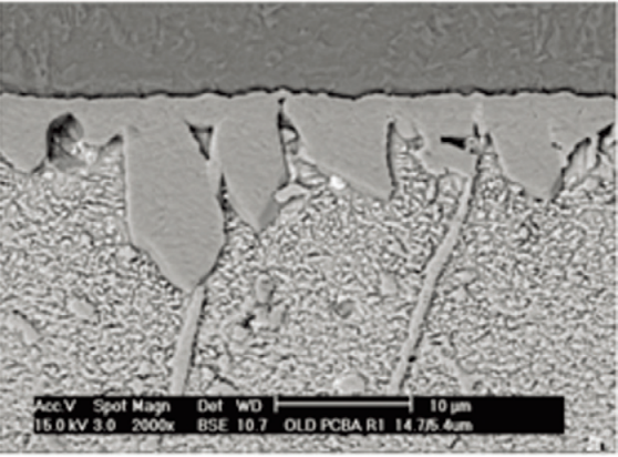
If the original IMC of the BGA is particularly thick, i.e. over 10μm, then the IMC is likely to develop into a wide and discontinuous lumpy IMC during reflow soldering, as shown in the diagram. This type of IMC will have around 20% lower tensile and shear strength relative to normal IMC and will be susceptible to fracture due to handling stresses during production turnaround and assembly.

Figure 2. Block IMC
Control method for cracking of BGA solder joints
1. Strict control of soldering temperature and time to avoid continuous IMC growth.
2. use low Ag+Ni lead-free solder. ag+Ni lead-free solder has excellent resistance to mechanical vibration. Ag is an element that accelerates the growth of IMC at the interface and Ni has an inhibiting effect on the production of Cu3 Sn. Low Ag+Ni can effectively stop the growth of IMC.
3. Reduce the weight of the components, increase the mechanism of parts such as brackets for heat sinks, increase the rigidity of the product during operation to avoid severe vibration, or change the production process such as the use of adhesive reinforcement, in order to improve the ability of the solder joint to resist mechanical stress.


 Back to list


