Failure Modes of Flip-Chip LED Solder Joints on Different Surface Finishes_Shenzhen Fitech

Failure Modes of Flip-Chip LED Solder Joints on Different Surface Finishes
LED is already a ubiquitous and indispensable device in life, and both lighting and display screens cannot be separated from the use of LEDs. With the increasing demand for LED products, LED chips tend to develop in the direction of high power, high density, and low cost. The implementation of a high-density chip layout strongly relies on the flip chip technology because the flip chip does not require the use of bonding wires, saving a lot of space. Surface finish is an important factor that cannot be ignored in affecting the soldering quality of flip-chip LEDs. This article briefly introduces the impacts of surface finishes on the failure modes of flip-chip LEDs.
Solder paste is required for chip soldering. During heating, the solder paste reacts with the surface finishes. It cannot be ignored that the interface reaction between the solder paste layer and surface finishes on LED chips with Au layers can affect and lead to changes in the shear strength of solder joints. To further understand the reason, Liu et al. soldered flip-chip LEDs with Au diodes onto ENIG and OSP using SAC305 solder paste and tested the solder joint shear strength.
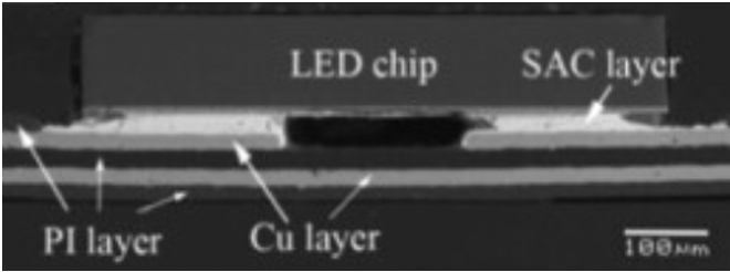
Figure 1. LED packaging structure.
Microstructure of solder joints
ENIG surface finish: When heated, the Au and Ni layers on the diode ENIG layer dissolved into the solder paste layer and became intermetallic compounds (Au, Ni) Sn4 IMC at the interface between the diode and the solder. In addition, Au and Ni gradually diffused to the interface between the solder and ENIG layer and formed dendritic Ni3Sn4 and (Au, Ni) Sn4 IMCs. After aging at 85 ℃ for 600 hours, Ni3Sn4 did not significantly grow due to the presence of AuSn4 inhibiting the interfacial IMC diffusion.
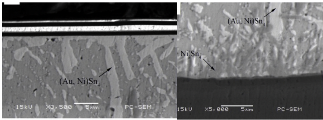
Figure 2. Microstructure of solder joint on ENIG surface finish.
OSP surface finish: During reflow soldering, the diode Au layer diffused to the solder joint and OSP interface. Therefore, the IMC consisted of (Au, Cu) Sn4, (Cu, Au) 6Sn5, and Ag3Sn. After the solder joint underwent the aging process, some inferior Cu3Sn formed at the interface between (Cu, Au) 6Sn5 and Cu.
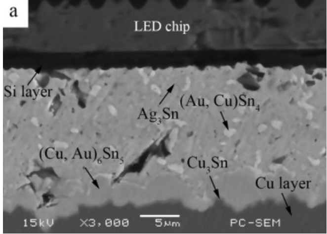
Figure 2. Microstructure of solder joint on OSP surface finish.
Shear force result
The solder joints on the ENIG surface finish had higher shear forces than those on OSP. As can be seen from Figure 4, the average shear force of solder joints on ENIG before aging was about 3.8N, which is much higher than the shear force of OSP solder joints before aging. As the aging process continued, the shear force of solder joints on both surface finishes decreased significantly, which is attributed to the coarsening and growth of IMC grains. The continuous coarsening and growth of IMC during aging enhanced the brittleness of the solder joints, making the solder layer the weakest part of the solder joints. When the solder joints were subjected to shear action, cracks formed in the solder layer and led to brittle fractures.
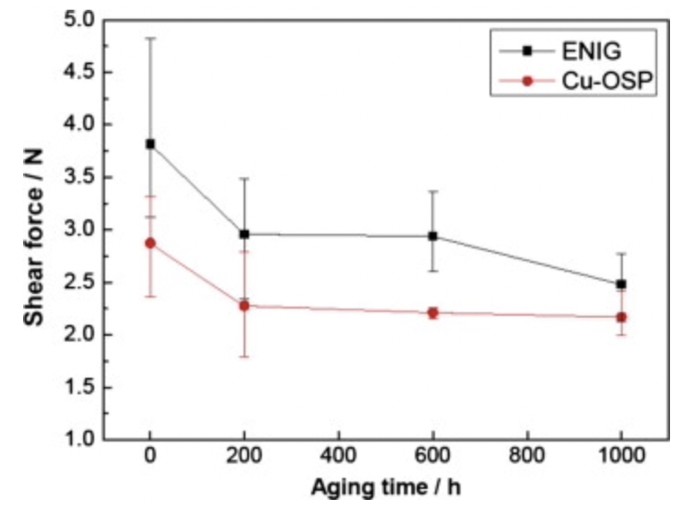
Figure 4. Shear forces of solder joints during aging.
High mechanical strength solder paste
Shenzhen Fitech is committed to providing customers with high-reliability solder pastes. Fitech’s low-temperature FL170/180/200 series, medium-temperature SAC305, high-temperature SnSb10, and other solder pastes have excellent mechanical strength and drop resistance, which make them applicable to a variety of packaging fields, such as micro optoelectronic displays, aerospace, automotive electronics, and so on. Welcome to contact us for more information.
Reference
Liu, Y., Sun, F.L., Zhang, H., Xin, T., A. Yuan, C. & Zhang, G.Q. (2015). Interfacial reaction and failure mode analysis of the solder joints for flip-chip LED on ENIG and Cu-OSP surface finishes. Microelectronics Reliability, vol. 55 (8), pp.1234-1240.




 Back to list


