Evolution of SAC305 under Electromigration and Thermal Shock_Shenzhen Fitech

Evolution of SAC305 under Electromigration and Thermal Shock_Shenzhen Fitech
Devices with increasingly high electronic packaging density, high current density, and small solder diameters pose issues such as electromigration that affect the reliability of solder joints. To address these issues, it is necessary to understand the microstructure evolution and failure mechanism of solder paste solder. When the solder is subjected to thermal shock, the combined effect of heat and electromigration will accelerate atomic diffusion and thermal stress formation, leading to excessive growth of intermetallic compounds (IMCs). In addition, thermal shock can cause inconsistent thermal expansion coefficients and accelerate soldering failure.
Experimental process
In order to gain a deeper understanding of the changes that occur in solder joints during thermal shock cycling and electric migration, Li et al. conducted a series of thermal shock cycling (-196 ℃ to 150 ℃) and electric migration tests (current density: 2 *10^4A/cm ^ 2) on SAC305 solder balls and analyzed the microstructure evolution and failure mechanism of solder joints. Figure 1 (a) shows a test module with a size of 20mm*20mm, consisting of four 300μm SAC305 solder balls. The pad diameter was 250μm, and the pads were coated with a nickel layer. Solder balls and chips were soldered through two reflow processes.
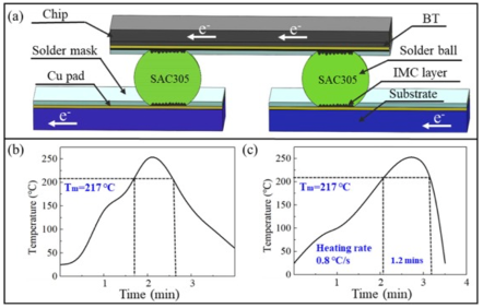
Figure 1. Test module and reflow profiles.
Experimental results
IMC structure
After energizing the SAC305 solder joint and conducting thermal shock cycles, a continuous (Cu, Ni) 6Sn5 IMC layer was detected at the anode interface on the left solder joint after 15 thermal cycles. Due to the electron flow driven by electromigration, Sn and Ni atoms migrated toward the anode and the morphology of the anode IMCs changed from scallop-shaped to planar. There was also a very thin (Ni, Cu) 3Sn4 layer at the cathode interface. For the right solder joint, (Ni, Cu) 3Sn4 and Cu6Sn5 were formed at the anode and cathode interfaces, respectively. The thickness of (Ni, Cu) 3Sn4 thickened with increasing electromigration time, which was attributed to the migration of solder atoms from the cathode to the anode with electron flow.
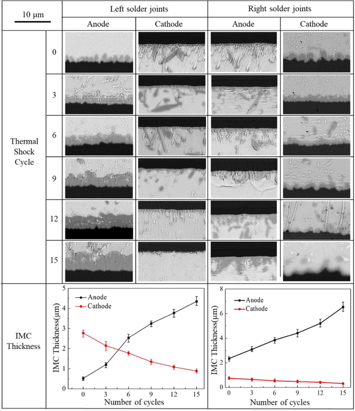
Figure 2. IMC evolution after thermal shock cycling.
Failure mode
A trace amount of Cu dissolution was observed at the upper interface of the left solder joint. The occurrence of local trace dissolution can be explained by the solidification and post-electromigration thermal cycling of SAC305 solder joints. The current tends to choose the path with the lowest resistance, which also promotes the accumulation of electrons at the position where the electron flow enters the solder joint, resulting in current crowding and Joule heat at the entrance. Therefore, due to the accumulation of Joule heat, local Cu dissolution of the solder joint was observed at the corner. In addition, due to CTE mismatch and lattice distortion of different structures, cracks propagate along the cathode interface, leading to solder joint failure. Similarly, the right solder joint also experienced local rapid dissolution of Cu solder pads after thermal cycling, and cracks formed at the anode interface.
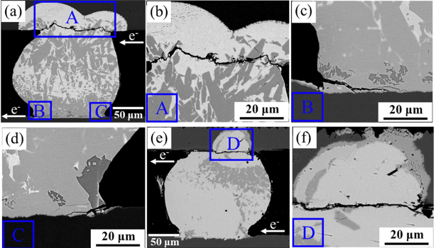
Figure 3. The failure mechanism of solder joints after 18 thermal shocks. (a-d) Left solder joint; (e-f) Right solder joint
Before 6 thermal cycles, slender fracture pits were found on the shear surface of the cathode side. Therefore, this fracture form belongs to ductile fracture. After 6 cycles, Ni3Sn4 IMC (red) was detected on the shear surface, indicating a transition of the fracture mode of the solder joint to ductile and brittle fracture. As the number of thermal cycles continues to increase, the number of Ni3Sn4 fractures increases. The anode side solder joint also has a similar fracture mechanism, which changed from ductile fracture to ductile and brittle fracture. The fracture mode indicates that the shear strength on the cathode side decreases with increasing cycles. However, the strength of the anode side first decreases and then increases, because the continuous extreme temperature causes twinning on the fracture surface and enhances the strength of the solder joint.
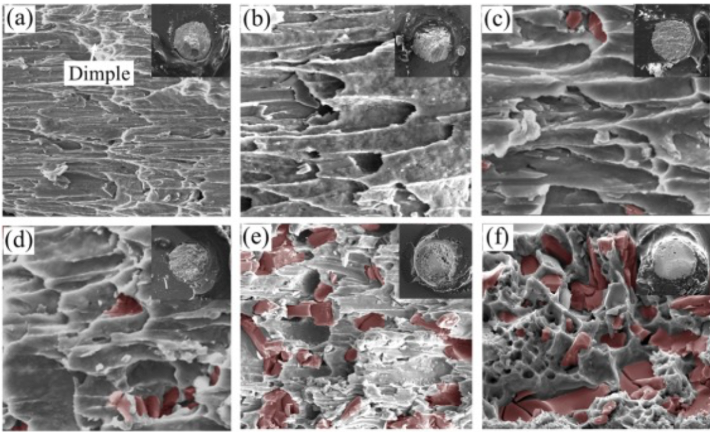
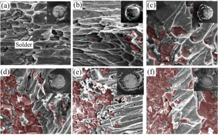
Figure 4. Shear failure diagram of the cathode side (upper) and anode side (lower) of the solder joint. (a) After reflowed; (b) 3 cycles; (c) 6 cycles; (d) 9 cycles; (e) 12 cycles; (f) 15 cycles.
Reference
Li, S.L., Hang, C.J., Zhang, W., Guan, Q.L., Tang, X.J., Yu, D., Ding, Y. & Wang, X.L. (2023). Current-induced solder evolution and mechanical property of Sn-3.0Ag-0.5Cu solder joints under thermal shock condition. Journal of Alloys and Compounds.




 Back to list


