The Thermal Annealing Impacts on SnAgCu Solder Paste
The Thermal Annealing Impacts on SnAgCu Solder Paste
Tin-silver-copper solder paste is a common lead-free solder paste widely used in medium-temperature soldering processes. The solder paste is deposited on the pads by processes such as printing or dispensing. After a reflow process, solid solder joints are formed. With the increasing frequency and duration of the use of electronic products, high requirements are placed on solder joint reliability. However, drop and impact often damage mobile electronics, resulting in cracks that can spontaneously propagate through the solder and cause device failure. Therefore, solder paste solder joints need to be able to withstand a sufficiently large impact. The analysis of solder joint microstructure is an important means to understand impact failure.
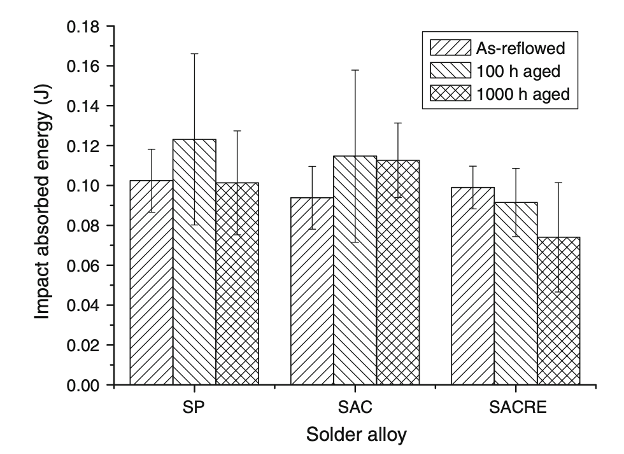
As the aging time increases, the microstructure of the SAC solder pastes significantly coarsens. It can be observed that Cu3Sn gradually grows at the interface between the Cu6Sn5 layer and the Cu substrate. After conducting dozens of experiments, it was found that thermal annealing is a process that can improve the impact reliability of solder joints. Zhang et al. (2009) expressed that SnAg3.8Cu0.7 solder paste impact toughness increased after annealing and subjected to an aging test at 150°C due to the coarsening of the microstructure. Zhang et al. found that when the aging time reached 1000h, the shock absorbed energy values of the SnAg3.8Cu0.7 solder joint were higher than that of the SnPb eutectic solder paste.

Figure 1. Impact absorbed energy values for different solder pastes (Zhang et al., 2009).
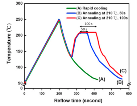
During the aging process of lead-free solder paste, the intermetallic compound Cu3Sn grows significantly, and the crack growth path moves from the SAC solder/IMC interface to the inside of the Cu6Sn5 layer. After 1000 hours, the area of the transgranular fracture mode is much smaller than that of 100 hours of aging, so the shock absorption energy value is higher. Chen et al. (2014) also performed 210°C annealing and aging tests for SAC/Cu composite solders. The reflow profile is shown in Figure 2.

Figure 2. Different annealing conditions for the SAC solder paste (Chen et al., 2014).

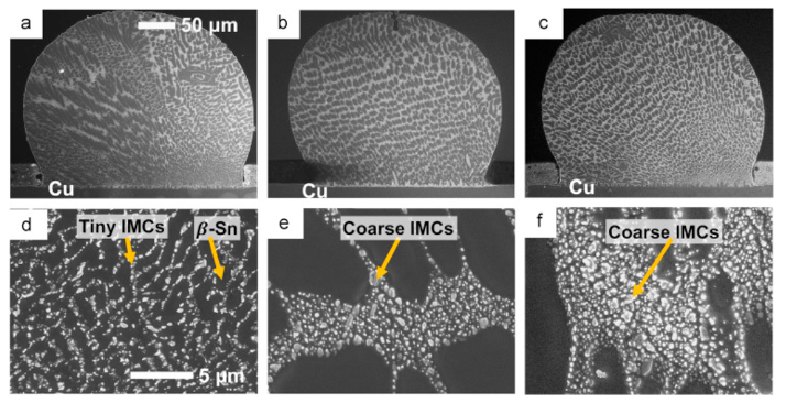
Figure 3. SEM images of SAC/Cu solder joints: (a) rapid cooling; (b, e) annealing for 50s; (c, f) annealing for 100s; (d-f) are the enlarge images of (a-c) SAC/Cu interfaces (Chen et al., 2014).
As the SAC/Cu solder joints were annealed at 210 °C for 50 and 100 s, the tiny precipitates gradually grew and coarsened, with a network-like distribution near the SAC/Cu interface (Figure 3). Compared with rapid cooling, annealing can increase the impact toughness of the solder joints. Chen et al. suggested that the driving force for the redistribution of the precipitates from the dot type to the network type is the IMC ripening and lowering of the surface energy so that the tiny Ag3Sn or Cu6Sn5 particle is combined. The progressively grown precipitates play an important role in enhancing the impact reliability of the solder joints.
Fitech is a professional manufacturer of packaging solder pastes. The solder paste products have stable performance, good welding effect, and outstanding solder joint reliability. Welcome to learn more details.
Reference
Chen, W.L., Yu, C.Y., Ho, C.Y., & Duh, J.G. (2014), “Effects of thermal annealing in the post-reflow process on microstructure, tin crystallography, and impact reliability of Sn–Ag–Cu solder joints”, Materials Science and Engineering: A, vol.613, pp.193-200.
Zhang N., Shi, Y.W., Lei, Y.P., Xia, Z.D., Guo, F., & Li, X.Y. (2009), “Effect of Thermal Aging on Impact Absorbed Energies of Solder Joints Under High-Strain-Rate Conditions”, Journal of Electronic Materials, vol.38(10), pp.2132-2147.


 Back to list


