Introduction of Electromigration of Lead-Free Solder Paste
Introduction of Electromigration of Lead-Free Solder Paste
With the rapid development of semiconductor packaging technology, the integration level of components is getting higher and higher. Under the background that consumers have higher requirements for the use of electronic products, more highly integrated products are undoubtedly sought-after. The advanced integration has many impacts on the package structure, such as a higher number of internal and external interconnects, which brings challenges to the reliability of the solder paste used for the package. Lead-free solder pastes are the mainstream solder product of packaging material manufacturers. However, due to the high level of integration and miniaturization of electronic products, electromigration has become a major culprit affecting the quality of soldering.
An important reason for electromigration in lead-free solder paste is the high current density. The miniaturization of components and the increase in the number of interconnects result in greater current densities, and the effects of electromigration become more pronounced. Electromigration is the movement of materials due to momentum transfer between electrons and metal atoms at high current densities. Due to uncompensated metal movement, voids will appear on the cathode side (inlet of electron flow), and metals deposit on the anode side (exit of electron flow), eventually leading to an open circuit and failure of the solder joint.
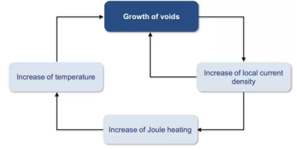
For flip chips, electromigration accelerates metal diffusion and affects IMC growth. As the under-bump metallization (UBM) is depleted and the RDL width is reduced, solder joints can suffer from void accumulation. High temperature also accelerates the growth of IMCs. The brittle IMCs produce cracks and voids in solder joints. What’s more, the Joule heating generated by the current increases the temperature of the components, which in turn accelerates electromigration. The presence of voids increases the resistance of the solder joint, which eventually leads to an open circuit. The mean time to failure can be determined by the following formula where t is the failure time, J is the current density, T is the temperature, k is the Boltzmann constant, A is the prefactor, n is the current density exponent, and Ea is the activation energy.


Figure 1. Failure mechanism of electromigration.
The copper pillar structure can improve electromigration performance. It mainly contains three advantages, including reducing current crowding to minimize local current density, reducing Joule heating, and providing a distance barrier so that solder paste cannot directly react with copper RDL (Darveaux et al., 2015). In addition, doping with some specific nano-enhancing particles has a positive effect on improving the anti-electromigration ability of solder pastes.
Fitech is a manufacturer dedicated to the production of ultra-fine solder pastes. Fitech can customize solder paste with different parameters according to customers’ needs and can provide solder paste products with high resistance to electromigration. Welcome to consult.
Reference
Darveaux, R., Hoang, J.V., Vijayakumar, B., & Skyworks. 2015, “ELECTROMIGRATION PERFORMANCE OF WLCSP SOLDER JOINTS”.


 Back to list


