How to Optimize the Reflow Time of Medium-Temperature Lead-Free Solder Paste

https://en.szfitech.com/
How to Optimize the Reflow Time of Medium-Temperature Lead-Free Solder Paste
The melting point of medium-temperature lead-free solder paste is between low-temperature lead-free solder paste and high-temperature lead-free solder paste. For manufacturers requiring multiple reflow packaging, the melting point of medium-temperature solder paste is about 210℃, which can be applied to the first reflow in multiple reflows. The melting point of SnAg3Cu0.5 lead-free solder paste is 217 ℃, which make it has better thermal fatigue resistance than SnPb under non-extreme conditions, and therefore SnAg3Cu0.5 solder paste is widely used. However, in the reflow process, the SAC solder paste will generate intermetallic compounds that can affect the mechanical strength of solder joints. Therefore, in order to ensure good reliability, the reflow profile of SAC solder paste needs to be optimized.
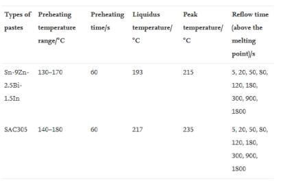
In order to determine the most appropriate reflow time, a series of experiments need to be completed. For example, Gong et al. (2021) compared the mechanical strength of solder joints of copper sheets after soldering with different reflow duration for SAC305 solder paste, and the result comparison between SAC305 and SnZn9Bi2.5In1.5 was conducted. The following table lists the parameters of reflow soldering. The shear strength test adopted the pushing velocity of 100μm/s, and the pushing tool moved along the horizontal direction at the height of 150μm above the base plate until the copper sheets were stripped.
Table 1. The reflow paramters of SAC305.

Conclusion
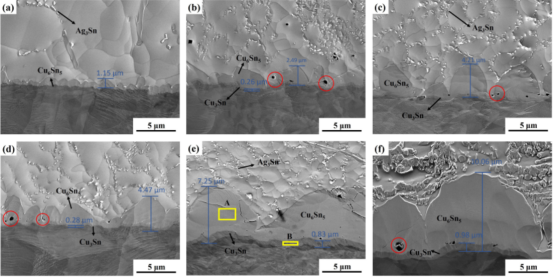
Continuous Cu6n5 growth occurred in the reflow soldering of SAC305 lead-free solder paste. As the reflow time (above the melting point) increased to longer than 50s, the Cu3Sn layer began to appear in the solder joints and grew continuously, and voids can be clearly seen (red circles). The formation mechanism of intermetallic compounds is related to the diffusion of metal components and interfacial reaction. During reflow soldering, Cu dissolves into the solder and reacts at the interface. Due to the high growth rate, Cu6Sn5 grains grow in an irregular scallop shape. With the increase of reflow time and the diffusion of Cu atoms along the grain boundary, Cu6Sn5 grains grow continuously. Cu6Sn5 will react with Cu to form Cu3Sn. Ag3Sn in the solder layer has no effect on the reliability, while the tiny Ag3Sn particles can refine the grain and enhance the reliability.

Figure 1. Change of intermetallic compund layers of lead-free solder joints. Reflow time: (a) 5s, (b) 50s, (c) 80s, (d) 120s, (e) 900s, (f) 1800s.
As shown in Figure 2, when the reflow time (above the melting point) was controlled at 50s, the shear strength of the SAC305 solder joint was maximized. Although the shear strength rose slightly when the reflow time was set to be 180s, the strength dropped precipitously with the further increase of the reflow time. Therefore, the reflow time of SAC305 solder paste can be roughly controlled at about 50s to maintain excellent shear strength of solder joints. SnZn9Bi2.5In1.5 solder paste has better shear strength than SAC305 solder paste, but it is still not been popularized and is only used as the control group.

Figure 2. Shear strength comparison.
Fitech is a leading provider of microelectronic and semiconductor packaging materials solutions. Fitech’s medium-temperature solder pastes, such as SAC305 and other products, have a good wetting effect, uniform powder particles, and high reliability after soldering. Welcome to the official website for more information.


 Back to list


