The Mechanical Property Consideration to Achieve High-Reliability Lead-Free Solder Joints
Shenzhen Fitech - Research Center - Shuquan Luo


The basic solder mechanical properties include stress and strain, creep resistance, and fatigue resistance. Shear strength is also an important factor in the reliability of solder joints because most solder joints are subjected to shear stress when used. Creep is another factor in solder joint reliability testing. Creep is the plastic deformation that occurs when temperature and stress are constant. This time-dependent deformation can happen at any temperature above absolute zero. However, creep is only manifested at "active" temperatures. Fatigue refers to the decrease in reliability, leading to the failure of solder joints under alternating stress. Fatigue cracking usually starts from several small cracks and enlarges under the cyclic action of stress, resulting in decreased solder joint reliability and failure of component soldering. Solders in electronic packaging and assembly are typically subject to low-cycle fatigue and high stress. Thermal fatigue is another test mode used to characterize solder. It is compulsory to test and analyze the shear strength, pull strength, creep, and other conditions of the solder joints to achieve high-reliability solder joints.


1.1 Shear Strength Test
Shear strength is an important factor that reflects the reliability of solder joints. The following figures represent the shear strength of Sn3.5Ag and Sn4.0Ag0.5Cu alloys on pads that have undergone the OSP process and Electroless Nickel Immersion Gold (ENIG) process.
[1]
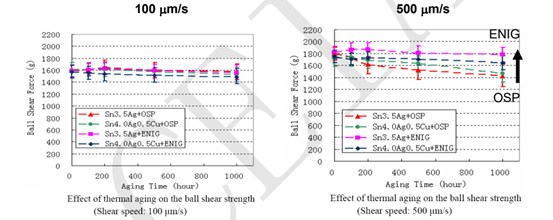
As shown in the figures above, the shear strength of the alloys on the pads with the ENIG surface treatment process is better than the pads with the OSP surface treatment process. The shear strengths of SAC alloy and SA alloy are similar. Shear strength decreases with aging.
1.2 Pull Strength Test
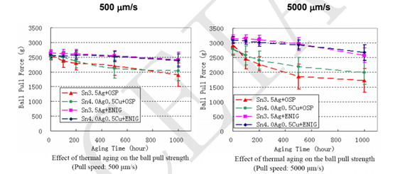
Pull strength critically reflects the reliability of solder joints. The following figures represent the pull strength of Sn3.5Ag and Sn4.0Ag0.5Cu alloys on the pads with the OSP and ENIG processes.
[2]
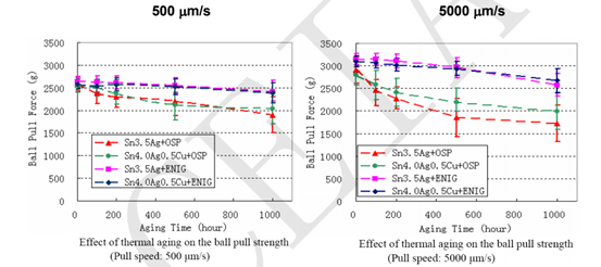
As shown in the figures above, the pull strength of the alloys on the pads with ENIG is better. The pull strengths of SAC alloy and SA alloy are similar. Pull strength decreases with aging. The pull speed increase causes a worse pull strength.
1.3 The Impacts of Shear Strength and Shear Velocity on IMC Thickness
The thickness of the IMC layer in the solder joint has a critical impact on the solder joint reliability. Both thick or thin IMC layers will negatively affect the stability and service life of the solder joints. The following figures show the effects of shear strength and shear speed on the IMC layer thickness.
[3]
It can be seen from the above figure that the faster the shear velocity, the greater the effect on the IMC layer thickness. However, alloy composition has a minute effect on the IMC layer thickness.
1.4 The Impacts of Pull Strength and Pull Velocity on IMC Thickness
The thickness of the IMC layer influences the reliability of solder joints. The impacts of tensile strength and tensile speed on the IMC layer thickness are shown below.
[4]
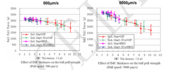
The pull test results highlight that the pull speed significantly affects the IMC layer thickness. The alloy composition has a negligible effect on IMC thickness.
1.5 The Comparison Between Shear Strength and Pull Strength Impacts on IMC Layer Thickness
The shear strength and pull strength have a significant impact on the IMC layer thickness. An experiment was conducted to detect the influences of shear strength and pull strength on the IMC layer thickness for two different alloys and surface treatment processes.
[5]
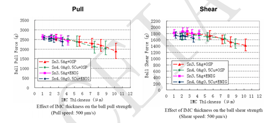
It can be concluded that the shear strength and pull strength hav a comparable impact on IMC layer thickness.


2.1 The Creep Data of Flip-Chip Solder Joints
The solder joint reliability is affected by creep. The following figures mention the creep data of flip-chip solder joints.
[6][7]
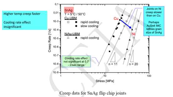

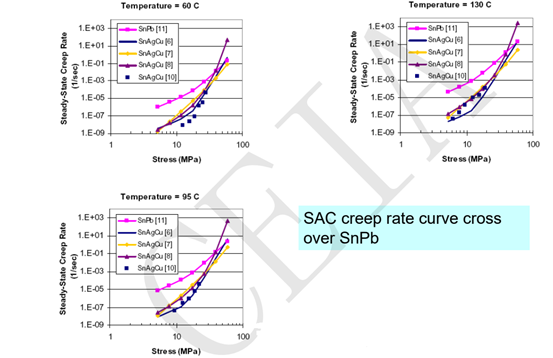
The intersection curves of SAC alloy and SnPb alloy representing creep are shown in the figures below.
[8]
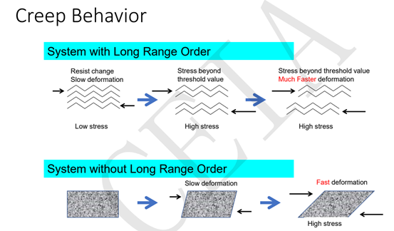
The creep phenomenon reduces the solder joint reliability. The occurrence of creep will be explained in the following. The solder joint deformation is positively correlated with the creep rate.
For better solder joint reliability, it should control the shear strength and tensile strength, as well as the thickness of the IMC layer, to make it meet the solder reliability requirements. When using electronic devices, the ambient temperature changes spontaneously. The power cycle of the chip influences the surrounding temperature. The thermal expansion coefficients of the chip and substrate are different. Therefore, thermal stress is generated in the solder joints and causes fatigue. Meanwhile, the melting point of the solder is relatively low compared with the ambient temperature. The solder joints will have obvious viscosity degradation, resulting in creep and solder joint fracture. The external failure mode is manifested as electrical signal transmission distortion, including poor electrical contacts, short circuits, and open circuits.
Fatigue and creep have interaction under certain conditions. Creep accelerates the formation and extension of cracks. The damage caused by cyclic cracking promotes the progress of creep, significantly shortening the cycle life. However, electronic products in the aerospace field are usually under harsher temperature cycle conditions. The fatigue and creep of solder joints have become an inherent danger of electronic product failure. Therefore, controlling the fatigue and creep of solder joints has become an important topic in electronic packaging.
Fitech has been focusing on microelectronics and semiconductor packaging solder for more than 20 years. Fitech is a world-leading packaging material and solution provider for microelectronics and semiconductors. It is a national high-tech enterprise deeply engaged in microelectronics and semiconductor packaging materials. It is the only electronic-grade packaging material manufacturer in the world that can manufacture T2-T10 ultra-fine solder powder. Fitech's solder paste, epoxy solder paste, and alloy solder powder are widely used in microelectronics and semiconductor packaging. The global SMT electronic chemical manufacturers, micro photoelectric manufacturers, and semiconductor packaging testers have recognized the products. However, the problems with microelectronics and semiconductor packaging materials are extensive. We only describe the common problems here. The issues involved may be different because of different technological processes. Welcome to communicate and discuss the specific question with our professionals. We hope to keep pace with the times with our partners and explore new problems, technologies, and complex processes together. Fitech strives to provide partners with professional and thoughtful microelectronics and semiconductor packaging and soldering materials services.
Reference
[1]Fubin Song and S. W. Ricky Lee, “Investigation of IMC Thickness Effect on the Lead-free Solder Ball Attachment Strength: Comparison between Ball Shear Test and Cold Bump Pull Test Results”, 56th ECTC Proceedings, P. 1196-1203, San Diego, CA, May 30-June 2, 2006
[2]Fubin Song and S. W. Ricky Lee, “Investigation of IMC Thickness Effect on the Lead-free Solder Ball Attachment Strength: Comparison between Ball Shear Test and Cold Bump Pull Test Results”, 56th ECTC Proceedings, P. 1196-1203, San Diego, CA, May 30-June 2, 2006
[3]Fubin Song and S. W. Ricky Lee, “Investigation of IMC Thickness Effect on the Lead-free Solder Ball Attachment Strength: Comparison between Ball Shear Test and Cold Bump Pull Test Results”, 56th ECTC Proceedings, P. 1196-1203, San Diego, CA, May 30-June 2, 2006
[4]Fubin Song and S. W. Ricky Lee, “Investigation of IMC Thickness Effect on the Lead-free Solder Ball Attachment Strength: Comparison between Ball Shear Test and Cold Bump Pull Test Results”, 56th ECTC Proceedings, P. 1196-1203, San Diego, CA, May 30-June 2, 2006
[5]Fubin Song and S. W. Ricky Lee, “Investigation of IMC Thickness Effect on the Lead-free Solder Ball Attachment Strength: Comparison between Ball Shear Test and Cold Bump Pull Test Results”, 56th ECTC Proceedings, P. 1196-1203, San Diego, CA, May 30-June 2, 2006
[6] S. Wiese, M. Roellig, K.-J. Wolter, " Creep of Eutectic SnAgCu in Thermally Treated Solder Joints", 55th ECTC, P.1272-1281, May 31-June 3, 2005
[7] S. Wiese, M. Roellig, K.-J. Wolter, " Creep of Eutectic SnAgCu in Thermally Treated Solder Joints", 55th ECTC, P.1272-1281, May 31-June 3, 2005
[8]Ahmer Syed, " Accumulated Creep Strain and Energy Density Based Thermal Fatigue Life Prediction Models for SnAgCu Solder Joints", 54th ECTC, P.737-746, June 1-4, 2004, Las Vegas, Nevada.


Ultra-Fine Solder Solutions Supplier for Microelectronics and Semiconductors




 Back to list


